How to Install a Double Din Head Unit and Reverse Camera
Posted: Sun May 12, 2013 2:08 pm
Again this is a situation of me finding very sketchy information on the Internet on the installation of a Double DIN Car Entertainment System with reverse camera into my Hilux. So I decided to document this process for those who may want to do a similar installation. This installation relates to the Unit I got from Stopshop but it seems as if most of them work the same. (Just a note on Stopshop’s terms and conditions. They expect that you should have the unit installed “professionally”. I have seen and experienced “professional installations” and would frankly rather do it myself and save me having to do it over again anyway. If the harness provided with the unit is not cut or damaged they will do warranty repairs locally but if it needs to be sent to the manufacturer for repairs they will require an invoice from a professional installer so take note that there is some risk in doing it yourself.)
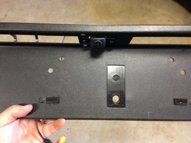
The biggest work by far is the installation of the reverse camera. The unit I specified is the “universal Toyota” camera so it was not simply a question of removing a number plate light and snapping the camera in place. I therefore had to make a little bracket in order to mount the camera where I wanted to. (Which was also the only really feasible spot to mount it anyway. The ideal being like the factory installed camera on the Heritage Edition Hilux, against the back of the tailgate, as it looks downward and gives a very clear reference of the position of the rear bumper.) The only remaining spot was to mount it on the number plate surround trim panel. I did this first as it is the most work. Here is a pic of the panel with the camera installed for reference.
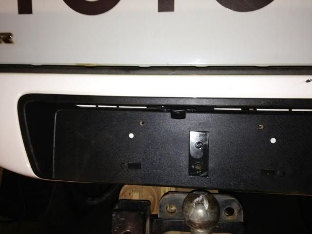
Start by removing the number plate and number plate holder. The number plate holder is screwed to the rear of the bumper with two screws. You need to remove these to be able to unclip the number plate surround/trim panel. Unclip the surround. It has square expanding lugs at the back that you need to compress to get it out without breaking it.
Next was to open the area where the camera is to be mounted by cutting away some of the plastic to match the shape of the camera body. This is easily achieved with a Stanley knife. You really only need to cut away a small amount to make sure the camera sits as close to the end as possible. I decided to mount it to the left of centre as it is closer to the main harness which runs along the length of the vehicle on the left hand side. The area where I removed the plastic is clearly visible in a later photo I will mark as such.
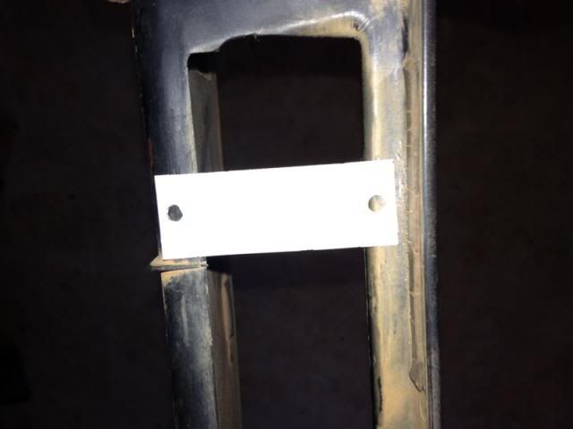
Next I cut a little plate that I attached to the holder with two stainless steel sunken head Allen screws. Mark the plate and drill the holes.
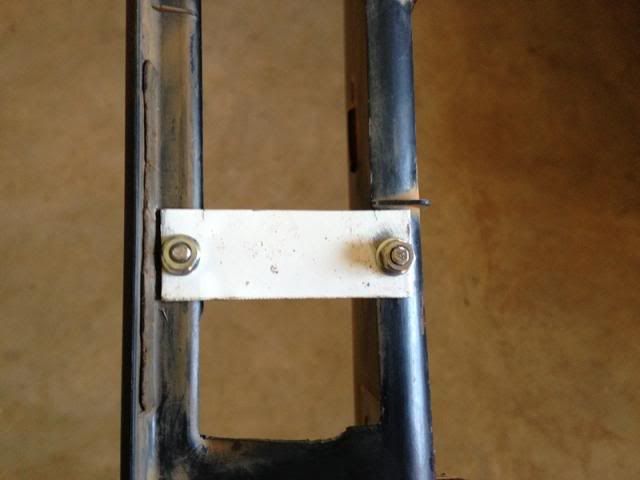
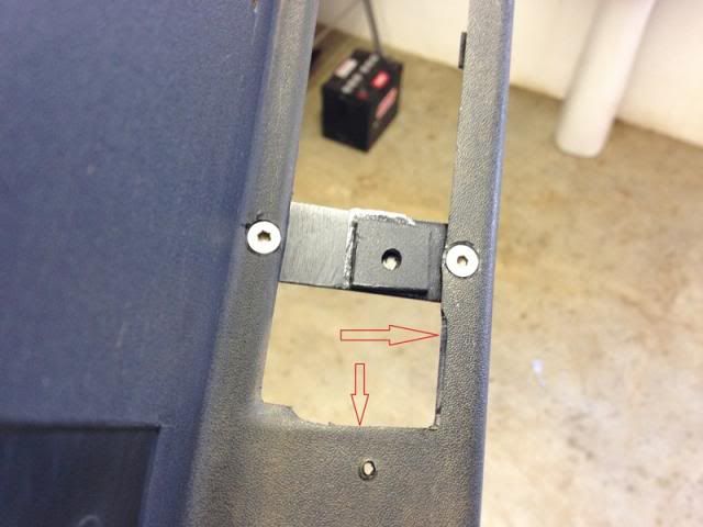
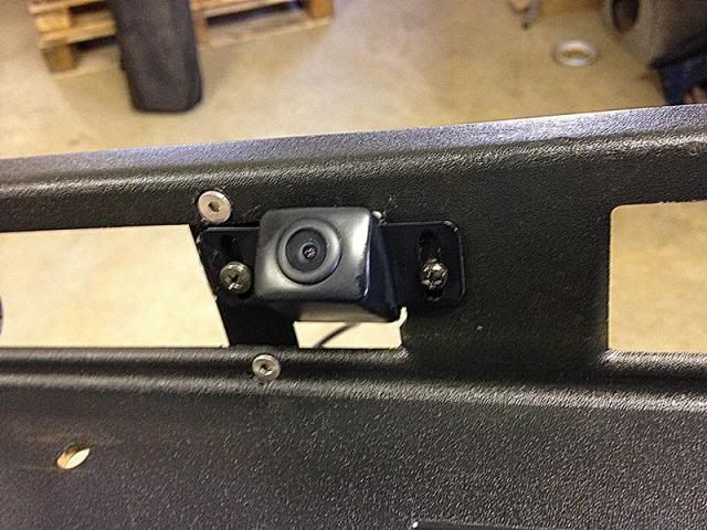
I then countersunk the holes to conceal the screws. After painting I installed the plate. I used some Loctite to make sure the small nuts stay put. I then drilled the holes for the camera after marking them and screwed in self tapping screws. These should be more than adequate to hold the camera as it is very light. I also cut a spacer from plastic and attached it to the plate with mounting tape to ensure the camera is mounted level. The arrows clearly indicate where I had to remove some plastic for the camera to mount flush as mentioned earlier.
Here are some pics with the camera installed in the trim plate.
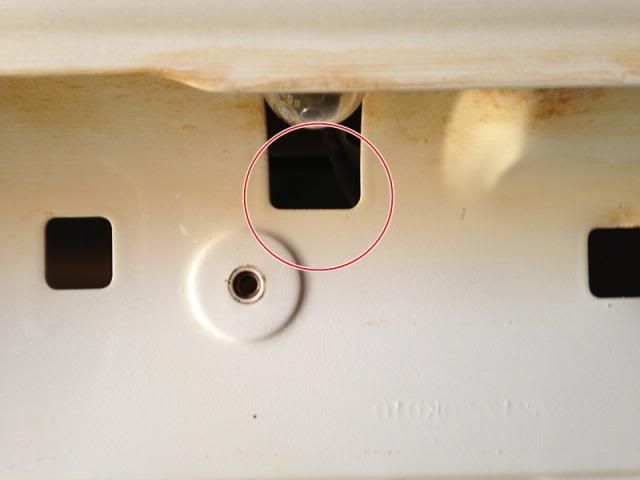
The Camera has two wires. A yellow RCA connector for the signal and a red plug for power to the camera. I routed the camera wires through the rectangular hole visible here.
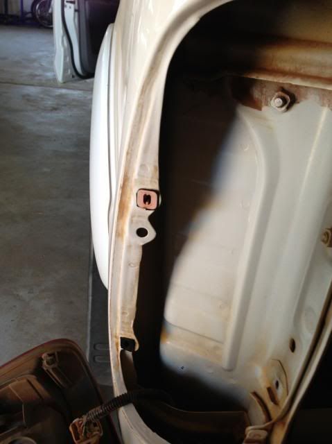
Next I removed the left rear light cluster by removing the two 10mm screws located here.
The light cluster is then pulled free by pulling straight back towards you. It is quite tight.
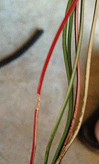
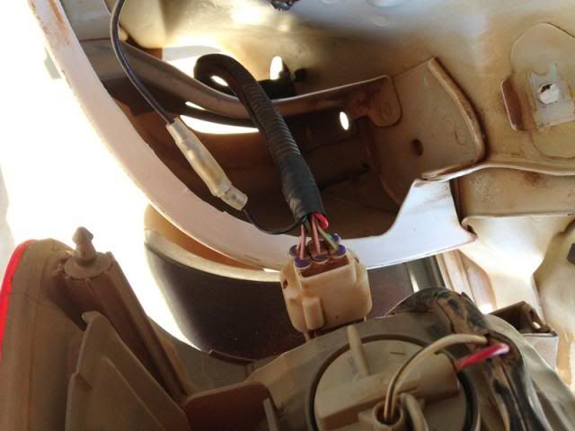
I then disconnected the electrical plug and pulled the light harness down underneath the car. I had to unclip two cable retainers to get the tail light harness free. I did this to make it easier to get to the wires to identify which is the reverse light signal. It is the red and white wire. I pulled the wires free from the ribbed sleeving and stripped some of the insulation off the red and white wire.
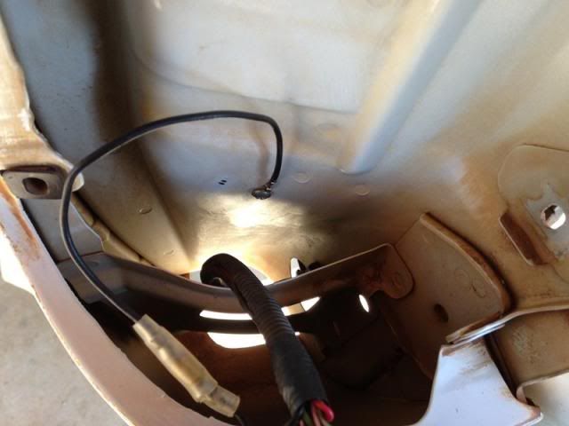
I then spliced and soldered the red wire which provides power to the camera in there. I considered doing the same with the black wire to the black and white negative wire of the harness but the supplier suggests that it is better to make a dedicated ground wire for the camera. I drilled a little hole in the body and mounted a ground wire I had made up there. I connected it to the camera ground with a push-in-connector. I then taped up the wires with insulation tape and inserted the wires including the wires for the camera into the original ribbed sleeve and attached the ground wire.
New wires in place in the exisitng sleeve.
Here is the new ground wire in place.
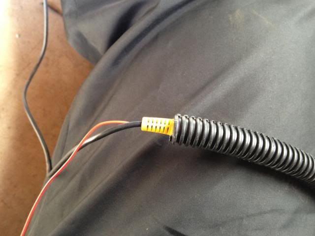
I bought ribbed sleeving that is thick enough to insert a RCA plug as the camera connects to the long cable (which runs to the front of the vehicle) by means of a power plug and a RCA plug. The idea is to be able to properly protect these connectors as they are under the car and exposed to the elements and road debris and you really don’t want those connectors to get wet and dirty as the camera will stop working very quickly. Here is a pic of how the plug fits into the sleeving as an example.
I connected the plugs and inserted them into the sleeving so that they are behind each other in the sleeve and taped it up properly.
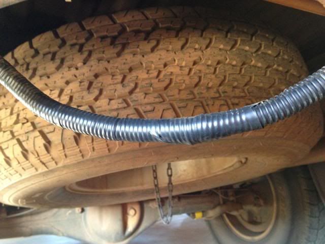
I then inserted the cable leading up to the camera into the sleeve to ensure that there is absolutely no area where the wiring is exposed. I left the cable splitter outside the sleeving as it would be easier to make a T there with the sleeving going forward to the cabin.
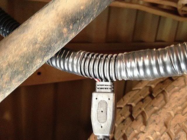
Here is the sleeving meeting up over the splitter.
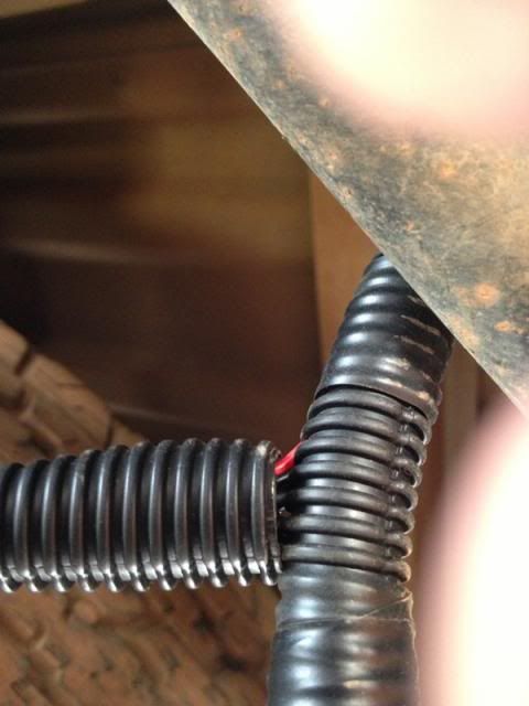
I then taped up all the ends of the sleeving and secured everything to the chassis and/or existing harness where best suited.
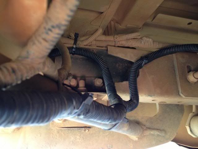
Next I inserted the rest of the cable into the sleeving and routed the cable through to the front of the vehicle. I used the same route as the existing harness except over the fuel tank where it is easier to run it along the chassis and secure it with cable ties.
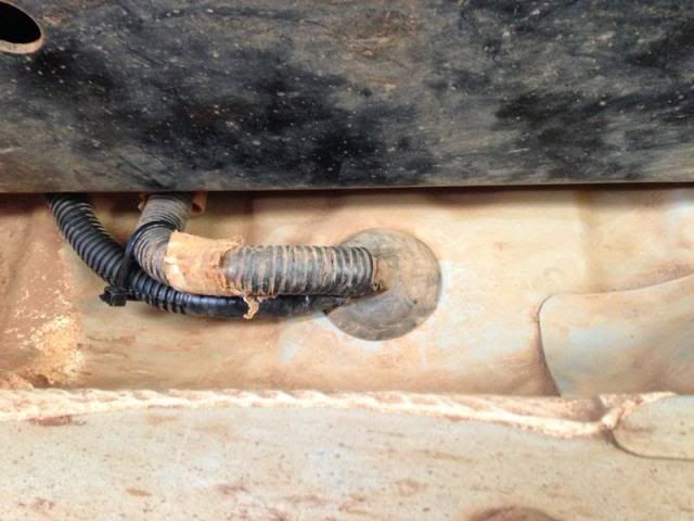
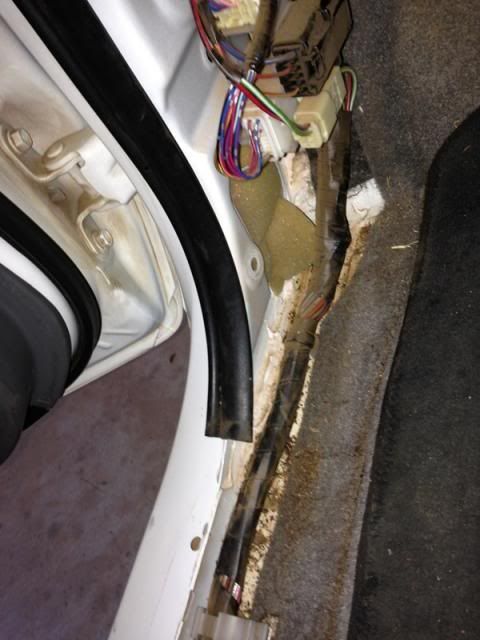
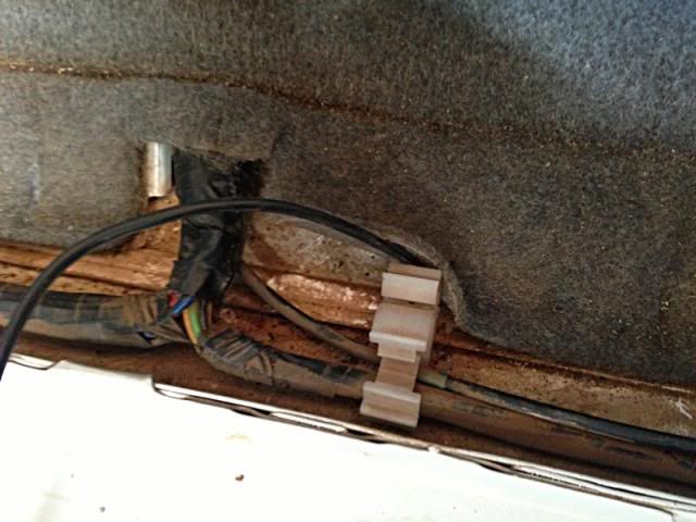
Under the front passenger seat is a grommet where the car’s harness goes into the cab. I routed the sleeving to this grommet.
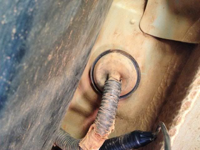
I tried to find a way not to cut the grommet but there is no way to unplug and remove the harness there so I made a small cut in the grommet on the rearward side. i.e. farthest away from the front wheel so that hopefully the water won’t splash in there. I worked the RCA plug through the slit in the grommet and pushed the cable into the cabin. I taped the new sleeving closed and secured it behind the existing harness with a cable tie.
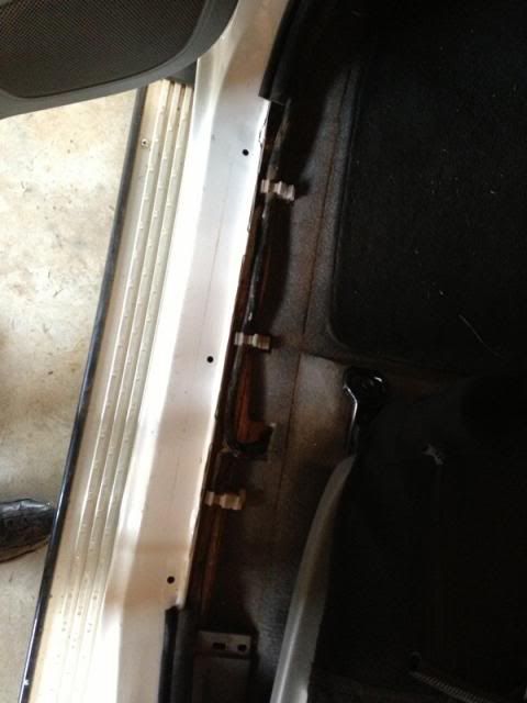
In order to get to the hole in the floor the door sill trim panel needs to be removed. The trim panel just clips into the sill so it is a simple question of lifting it up to unclip the clips.
It is also a good idea to remove the front left kick panel at this stage as well. The front kick panel has one plastic nut holding it in place and two clips. Simply pull off the after removing the plastic nut.
To remove the cubby hole is also very easy. It just clips into its hinges so it is a simple matter of opening the cubby and lifting it up. Then tilt it slightly sideways and remove. Now there is ample space to pull all the wires through.
To get to the hole under the seat simply lift up the carpet. The hole is close to the side and is easy to reach. I then threaded the cable through and reinstalled the grommet.
The cable is now routed along with the existing harness to under the dash. Before routing it to the head unit I decided to install the GPS antenna first and then to route the two wires together.
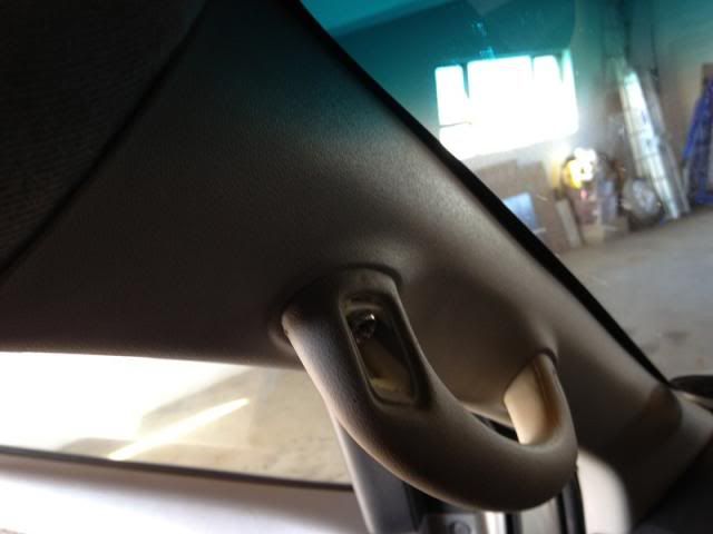
To install the GPS antenna it is necessary to remove the trim panel against the A-Pillar on the passenger side. I decided to install the antenna against the A-pillar underneath the panel so that no antenna is visible. To remove the panel gently pry off the caps on the handle. Be careful not to mar them. Lift them up from the front with a small screwdriver. Then remove the two 10mm screws holding the handle.
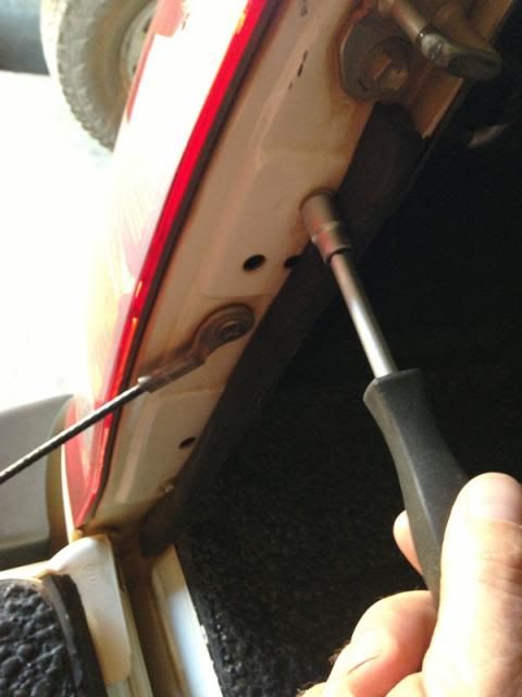
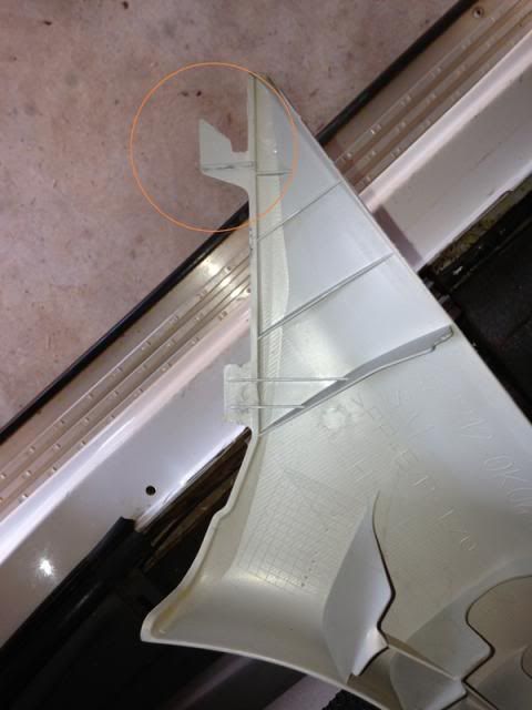
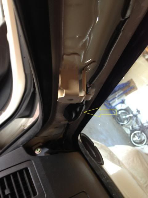
The panel can now be pulled away from the pillar as it is held with clips at the top and in the middle. To remove the panel at the bottom it needs to be tilted slightly forward to unhook the tab that hooks into the front of the dashboard and then remove the panel by pulling it towards the rear. Here is a pic of the tab mentioned which should help to understand how to pull out the panel. Circled.
This is a picture of the A-Pillar with panel removed. The GPS antenna is visible in its position marked with the arrow.
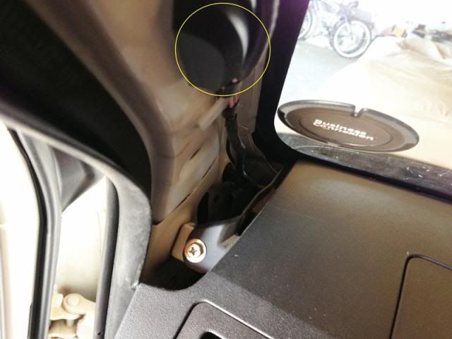
This opens a space to where the cable of the antenna can be pulled through between the A-Pillar and the dashboard. The magnetic base of the antenna sticks to the metal of the A-Pillar. Route the cable through to the foot well. The GPS antenna is also visible here. (Circled)
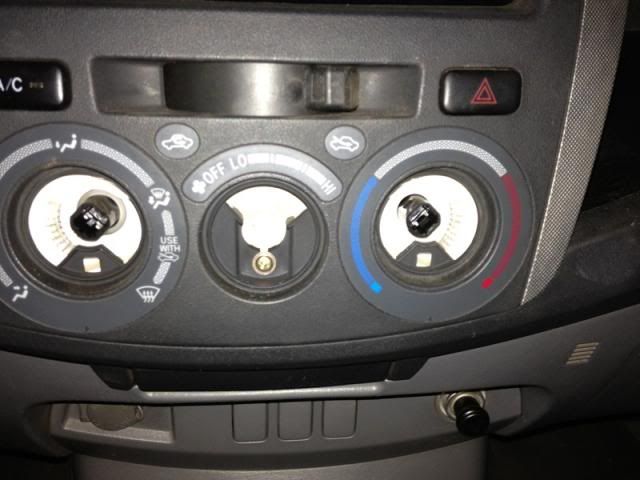
Now for the fun part. Removing the Head Unit. To remove the trim panel that surrounds the head unit it is necessary to pull out the temperature control knobs. They are easy to pull out. There is a Philips screw underneath the middle knob.
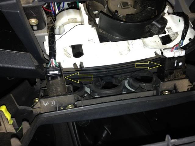
Remove the screw and pull the panel free towards you. It is quite easy if you grip the panel where the knobs go. Once the clips come free, grip the panel in the region of the air vents and pull out those clips. Unclip the plugs for the aircon and hazard switches. (Arrowed) The whole panel is now free.
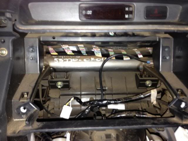
Remove the four 10mm screws securing the head unit. Be careful not to drop them as you will end up having to remove all kinds of panels to get to them. (Don’t ask me how I know). Pull the head unit towards you and remove the two plugs and the aerial cable from the head unit. (On later models with controls on the steering wheel there is a third plug that needs to be removed.)
This opens up a large area where it is very easy to work in to route the wires and tidy up before installing the new head unit.
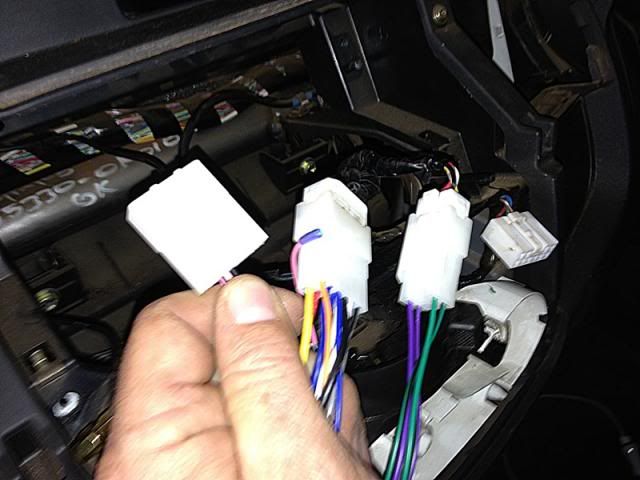
If you made sure that you ordered the correct model the plugs on the harness provided with the new unit should fit perfectly. They did on mine. The third plug I am holding is the one for the steering wheel controls.
Now it is time to route all the wires through under the dash to the area where the head unit goes. Be careful of sharp edges and don’t be shy with the cable ties. Put the iPod Cable and the USB cable in place too. I routed them through to the cubby hole area as I am going to let them lie loose in the cubby for easy access.
The RCA input of the head unit plug is clearly marked “CCD In” and the brown loose wire is also marked “CCD in”. The brown wire must get a 12V signal to switch the display over to the reverse camera when the car is put in reverse. The cable that came with the unit also included a wire running the length of the cable which means you already have a 12v signal on it as it is the same wire that powers the camera. I soldered a female lug onto it as well as a male lug onto the brown wire to connect the two. Now I connected the two harnesses to the existing harness. The provided harness also has three plugs (one for the steering wheel controls). I connected the red wire coming from the rear with the brown wire and made sure that is properly insulated. I used a sleeve which I taped up as I do not want a live 12V chafing on any bare grounded metal. The provided harness also has two other loose wires. A pink one which is labelled “Brake Control”. Apparently this one should be grounded if you want the TV to work whilst driving. I did not connect this wire as I do not intend watching TV in any event as there is preciously little to watch on the free to air channels and secondly don’t think it is the greatest idea to watch TV whilst driving. I left it as is. The other, a blue one, is to provide a power up signal to an external amp which I do not have. I also insulated all the other RCA input and output connectors with insulation tape as I do not want any potential short circuits. I realise that this is unlikely but I do not like to take any chances.
Now tidy up the old harness as there is considerably more cable with the new harnesses connected. I used cable ties throughout as I do not want chafed wires or strange rattles. Fortunately there is a lot of space above, behind and below the head unit.
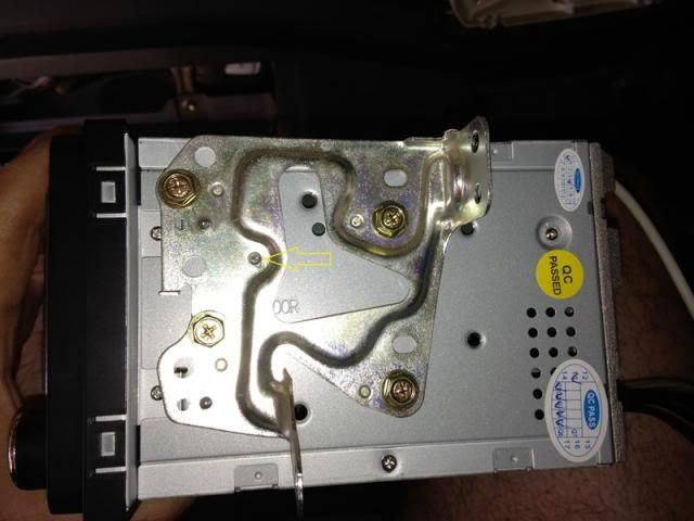
The brackets attached to the old head unit needs to be removed in order to use them on the new unit. This is easily achieved and they fit in the same position on the new unit. The only issue was that there is a punched protrusion in the middle that does not have a corresponding hole in the body of the new unit. I simply grinded it flush on both brackets and mounted the brackets to the new unit. The punched pin I had to grind flush is marked with an arrow.
Now place the new unit in position and connect all the wires. The two plugs of the new harness, the GPS antenna, the reverse camera RCA connector, the iPod cable (make sure it is firmly inserted till it clicks) and the USB Cable. This unit also has a separate USB cable for a 3G modem which is attached to the unit. Route this cable through to the cubby hole as well. Remember to also connect the radio antenna.
Once you are sure all the wires are out of the way slide the head unit into place and secure it with the 4 screws.
Now it is a simple matter of replacing all the panels you removed.
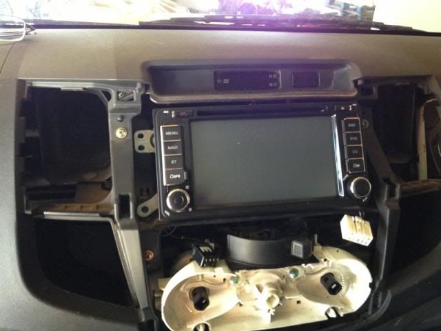
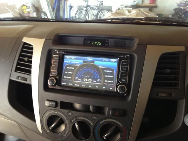
There is the unit installed.
The view from the reverse camera.
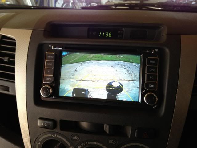
The built in gradings (yellow reference lines visible on the camera view) are surprisingly accurate and quite easy to use. They are however a little conservative so if you stop with an object aligned with the “stop line” on the camera you will never bump your car. The angle of view is also surprisingly wide. The position of the camera works quite well. All in all I am very happy with this upgrade.
I used exactly 4 meters of ribbed sleeving but get 5 to give you some leeway. The only other additional materials I needed was a 1mm metal plate, some screws, two male/female push connectors, some insulation tape and a short length of wire for the ground wire.
The biggest work by far is the installation of the reverse camera. The unit I specified is the “universal Toyota” camera so it was not simply a question of removing a number plate light and snapping the camera in place. I therefore had to make a little bracket in order to mount the camera where I wanted to. (Which was also the only really feasible spot to mount it anyway. The ideal being like the factory installed camera on the Heritage Edition Hilux, against the back of the tailgate, as it looks downward and gives a very clear reference of the position of the rear bumper.) The only remaining spot was to mount it on the number plate surround trim panel. I did this first as it is the most work. Here is a pic of the panel with the camera installed for reference.

Start by removing the number plate and number plate holder. The number plate holder is screwed to the rear of the bumper with two screws. You need to remove these to be able to unclip the number plate surround/trim panel. Unclip the surround. It has square expanding lugs at the back that you need to compress to get it out without breaking it.
Next was to open the area where the camera is to be mounted by cutting away some of the plastic to match the shape of the camera body. This is easily achieved with a Stanley knife. You really only need to cut away a small amount to make sure the camera sits as close to the end as possible. I decided to mount it to the left of centre as it is closer to the main harness which runs along the length of the vehicle on the left hand side. The area where I removed the plastic is clearly visible in a later photo I will mark as such.
Next I cut a little plate that I attached to the holder with two stainless steel sunken head Allen screws. Mark the plate and drill the holes.


I then countersunk the holes to conceal the screws. After painting I installed the plate. I used some Loctite to make sure the small nuts stay put. I then drilled the holes for the camera after marking them and screwed in self tapping screws. These should be more than adequate to hold the camera as it is very light. I also cut a spacer from plastic and attached it to the plate with mounting tape to ensure the camera is mounted level. The arrows clearly indicate where I had to remove some plastic for the camera to mount flush as mentioned earlier.

Here are some pics with the camera installed in the trim plate.


The Camera has two wires. A yellow RCA connector for the signal and a red plug for power to the camera. I routed the camera wires through the rectangular hole visible here.

Next I removed the left rear light cluster by removing the two 10mm screws located here.

The light cluster is then pulled free by pulling straight back towards you. It is quite tight.

I then disconnected the electrical plug and pulled the light harness down underneath the car. I had to unclip two cable retainers to get the tail light harness free. I did this to make it easier to get to the wires to identify which is the reverse light signal. It is the red and white wire. I pulled the wires free from the ribbed sleeving and stripped some of the insulation off the red and white wire.

I then spliced and soldered the red wire which provides power to the camera in there. I considered doing the same with the black wire to the black and white negative wire of the harness but the supplier suggests that it is better to make a dedicated ground wire for the camera. I drilled a little hole in the body and mounted a ground wire I had made up there. I connected it to the camera ground with a push-in-connector. I then taped up the wires with insulation tape and inserted the wires including the wires for the camera into the original ribbed sleeve and attached the ground wire.
New wires in place in the exisitng sleeve.

Here is the new ground wire in place.

I bought ribbed sleeving that is thick enough to insert a RCA plug as the camera connects to the long cable (which runs to the front of the vehicle) by means of a power plug and a RCA plug. The idea is to be able to properly protect these connectors as they are under the car and exposed to the elements and road debris and you really don’t want those connectors to get wet and dirty as the camera will stop working very quickly. Here is a pic of how the plug fits into the sleeving as an example.

I connected the plugs and inserted them into the sleeving so that they are behind each other in the sleeve and taped it up properly.

I then inserted the cable leading up to the camera into the sleeve to ensure that there is absolutely no area where the wiring is exposed. I left the cable splitter outside the sleeving as it would be easier to make a T there with the sleeving going forward to the cabin.

Here is the sleeving meeting up over the splitter.

I then taped up all the ends of the sleeving and secured everything to the chassis and/or existing harness where best suited.

Next I inserted the rest of the cable into the sleeving and routed the cable through to the front of the vehicle. I used the same route as the existing harness except over the fuel tank where it is easier to run it along the chassis and secure it with cable ties.
Under the front passenger seat is a grommet where the car’s harness goes into the cab. I routed the sleeving to this grommet.

I tried to find a way not to cut the grommet but there is no way to unplug and remove the harness there so I made a small cut in the grommet on the rearward side. i.e. farthest away from the front wheel so that hopefully the water won’t splash in there. I worked the RCA plug through the slit in the grommet and pushed the cable into the cabin. I taped the new sleeving closed and secured it behind the existing harness with a cable tie.

In order to get to the hole in the floor the door sill trim panel needs to be removed. The trim panel just clips into the sill so it is a simple question of lifting it up to unclip the clips.

It is also a good idea to remove the front left kick panel at this stage as well. The front kick panel has one plastic nut holding it in place and two clips. Simply pull off the after removing the plastic nut.

To remove the cubby hole is also very easy. It just clips into its hinges so it is a simple matter of opening the cubby and lifting it up. Then tilt it slightly sideways and remove. Now there is ample space to pull all the wires through.
To get to the hole under the seat simply lift up the carpet. The hole is close to the side and is easy to reach. I then threaded the cable through and reinstalled the grommet.

The cable is now routed along with the existing harness to under the dash. Before routing it to the head unit I decided to install the GPS antenna first and then to route the two wires together.
To install the GPS antenna it is necessary to remove the trim panel against the A-Pillar on the passenger side. I decided to install the antenna against the A-pillar underneath the panel so that no antenna is visible. To remove the panel gently pry off the caps on the handle. Be careful not to mar them. Lift them up from the front with a small screwdriver. Then remove the two 10mm screws holding the handle.

The panel can now be pulled away from the pillar as it is held with clips at the top and in the middle. To remove the panel at the bottom it needs to be tilted slightly forward to unhook the tab that hooks into the front of the dashboard and then remove the panel by pulling it towards the rear. Here is a pic of the tab mentioned which should help to understand how to pull out the panel. Circled.

This is a picture of the A-Pillar with panel removed. The GPS antenna is visible in its position marked with the arrow.

This opens a space to where the cable of the antenna can be pulled through between the A-Pillar and the dashboard. The magnetic base of the antenna sticks to the metal of the A-Pillar. Route the cable through to the foot well. The GPS antenna is also visible here. (Circled)

Now for the fun part. Removing the Head Unit. To remove the trim panel that surrounds the head unit it is necessary to pull out the temperature control knobs. They are easy to pull out. There is a Philips screw underneath the middle knob.

Remove the screw and pull the panel free towards you. It is quite easy if you grip the panel where the knobs go. Once the clips come free, grip the panel in the region of the air vents and pull out those clips. Unclip the plugs for the aircon and hazard switches. (Arrowed) The whole panel is now free.

Remove the four 10mm screws securing the head unit. Be careful not to drop them as you will end up having to remove all kinds of panels to get to them. (Don’t ask me how I know). Pull the head unit towards you and remove the two plugs and the aerial cable from the head unit. (On later models with controls on the steering wheel there is a third plug that needs to be removed.)
This opens up a large area where it is very easy to work in to route the wires and tidy up before installing the new head unit.

If you made sure that you ordered the correct model the plugs on the harness provided with the new unit should fit perfectly. They did on mine. The third plug I am holding is the one for the steering wheel controls.

Now it is time to route all the wires through under the dash to the area where the head unit goes. Be careful of sharp edges and don’t be shy with the cable ties. Put the iPod Cable and the USB cable in place too. I routed them through to the cubby hole area as I am going to let them lie loose in the cubby for easy access.
The RCA input of the head unit plug is clearly marked “CCD In” and the brown loose wire is also marked “CCD in”. The brown wire must get a 12V signal to switch the display over to the reverse camera when the car is put in reverse. The cable that came with the unit also included a wire running the length of the cable which means you already have a 12v signal on it as it is the same wire that powers the camera. I soldered a female lug onto it as well as a male lug onto the brown wire to connect the two. Now I connected the two harnesses to the existing harness. The provided harness also has three plugs (one for the steering wheel controls). I connected the red wire coming from the rear with the brown wire and made sure that is properly insulated. I used a sleeve which I taped up as I do not want a live 12V chafing on any bare grounded metal. The provided harness also has two other loose wires. A pink one which is labelled “Brake Control”. Apparently this one should be grounded if you want the TV to work whilst driving. I did not connect this wire as I do not intend watching TV in any event as there is preciously little to watch on the free to air channels and secondly don’t think it is the greatest idea to watch TV whilst driving. I left it as is. The other, a blue one, is to provide a power up signal to an external amp which I do not have. I also insulated all the other RCA input and output connectors with insulation tape as I do not want any potential short circuits. I realise that this is unlikely but I do not like to take any chances.
Now tidy up the old harness as there is considerably more cable with the new harnesses connected. I used cable ties throughout as I do not want chafed wires or strange rattles. Fortunately there is a lot of space above, behind and below the head unit.
The brackets attached to the old head unit needs to be removed in order to use them on the new unit. This is easily achieved and they fit in the same position on the new unit. The only issue was that there is a punched protrusion in the middle that does not have a corresponding hole in the body of the new unit. I simply grinded it flush on both brackets and mounted the brackets to the new unit. The punched pin I had to grind flush is marked with an arrow.

Now place the new unit in position and connect all the wires. The two plugs of the new harness, the GPS antenna, the reverse camera RCA connector, the iPod cable (make sure it is firmly inserted till it clicks) and the USB Cable. This unit also has a separate USB cable for a 3G modem which is attached to the unit. Route this cable through to the cubby hole as well. Remember to also connect the radio antenna.
Once you are sure all the wires are out of the way slide the head unit into place and secure it with the 4 screws.

Now it is a simple matter of replacing all the panels you removed.
There is the unit installed.


The view from the reverse camera.

The built in gradings (yellow reference lines visible on the camera view) are surprisingly accurate and quite easy to use. They are however a little conservative so if you stop with an object aligned with the “stop line” on the camera you will never bump your car. The angle of view is also surprisingly wide. The position of the camera works quite well. All in all I am very happy with this upgrade.
I used exactly 4 meters of ribbed sleeving but get 5 to give you some leeway. The only other additional materials I needed was a 1mm metal plate, some screws, two male/female push connectors, some insulation tape and a short length of wire for the ground wire.